Operating Pressure and Design Pressure of Atmospheric Tanks According to API 650
José Félix Acevedo B.
2/2/20257 min read
1. Introduction
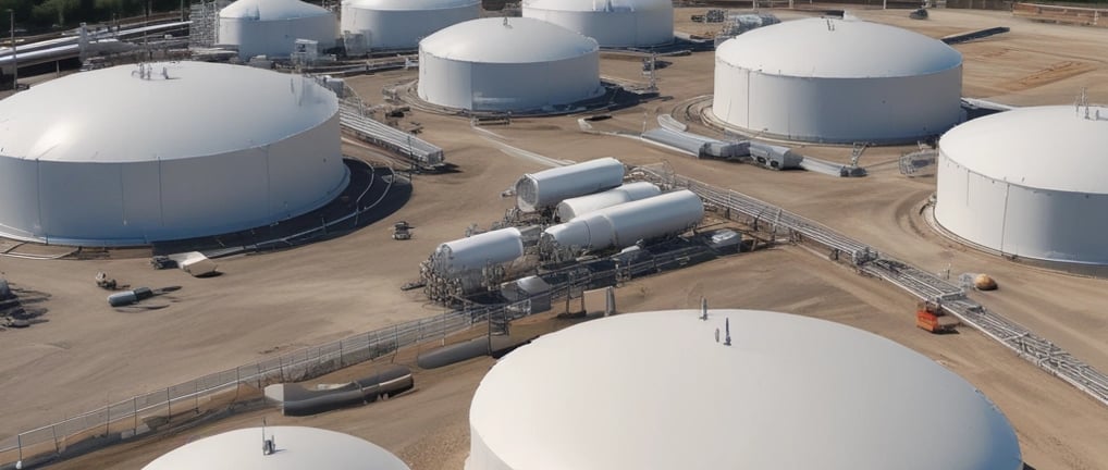
Atmospheric storage tanks designed under API 650 are used to store liquids under specific pressure and temperature conditions. However, the design, operation, and safety features vary depending on the type of tank and the devices installed, such as open vents, pressure and vacuum relief valves, flame arresters, emergency vents, and more. This article discusses in detail the types of tanks, associated pressures, and specific considerations for different configurations, organized into case studies.
2. Types of tanks according to API 650
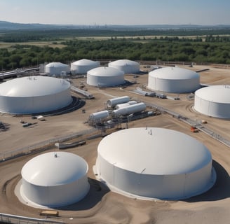
Paragraph 1.1.1 of the general scope of API 650 classifies tanks for unrefrigerated service as vertical cylindrical tanks, which may be:
Closed tanks: With fixed roof.
Open-top tanks: Designed to operate at pressures close to atmospheric pressures.
These tanks typically operate at approximately atmospheric internal pressures, although they can be designed to withstand internal pressures up to 18 kPa (2.5 psi) per the requirements of API 650 Annex F.
Closed tank configurations:
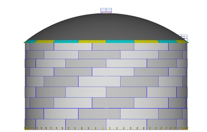
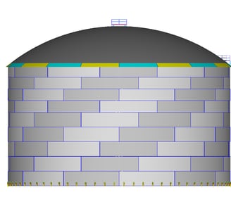
Carbon steel conical roof tanks: They can be supported or self-supported.
Carbon steel dome or umbrella roof tanks.
Aluminum geodesic dome roof tanks.
Open-top tank configurations.
Open tanks.
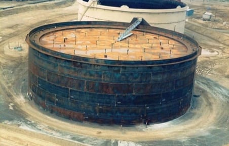
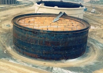
Tanks with external floating roofs: The most common are pontoon types and double deck types.
In addition, there are closed tanks with internal floating roofs, which combine fixed and floating roofs to minimize evaporation, reduce polluting emissions and reduce the risk of explosion or fire. These tanks are classified as fixed-roof tanks with internal floating roofs.
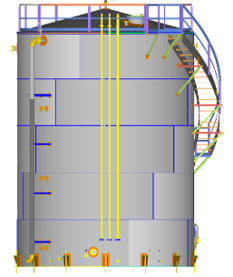
External Floating Roof Tank
3. API 2000 Venting Requirements
The API 2000 standard regulates venting systems in storage tanks, classifying them into two main categories:
Normal Venting: Handles pressure changes during filling, emptying, and/or thermal fluctuations.
Emergency Venting: Designed to relieve critical pressures caused by events such as exposure of the tank to fire or external heat sources that could cause thermal expansion of the contents.
Causes of overpressure or vacuum
Changes in temperature and ambient pressure.
Filling and emptying operations.
Failures in venting systems or accidental blockage.
Exposure to fire.
In tanks that store flammable liquids, API 2000 also recommends the use of flame arresters to prevent risks associated with the ignition of vapors.
4. Venting Devices Used in Storage Tanks
API 2000 classifies venting systems into two main types:
1. Pressure and vacuum valves.
They are used to relieve pressure, vacuum, or both.
They can be direct driven or pilot-operated.
They provide protection against overpressure and/or vacuum in low-pressure tanks, as well as minimizing product losses (also known as conservation venting).
.In critical situations, oversized valves (16" to 24") can be used to provide emergency venting and/or allow access to the tank during inspections.
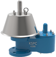

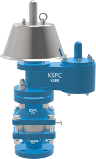
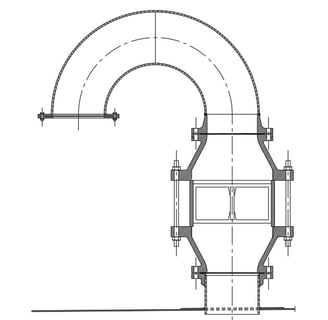
Pressure and Vacuum Relief Valve
Pressure and Vacuum Relief Valve with Flame Arrester
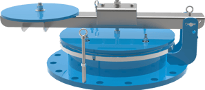
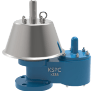
Emergency Vent Cover
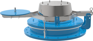
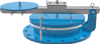
Emergency Vent Cover with Vacuum Relief
2. Open vents
Designed to operate at atmospheric pressure.
They are equipped with accessories to prevent the entry of water, snow, insects or birds, such as hoods, Chinese hats and goose neck.
They are commonly used in tanks that store non-flammable liquids, although they can be combined with flame arresting if flammable vapors are present.
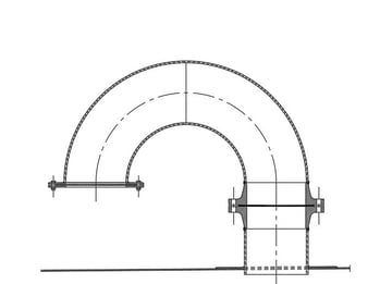
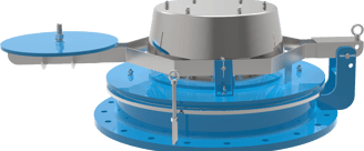
Open Vent
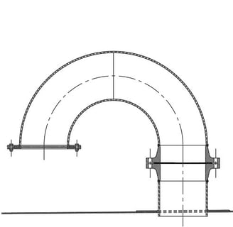
Goose Neck
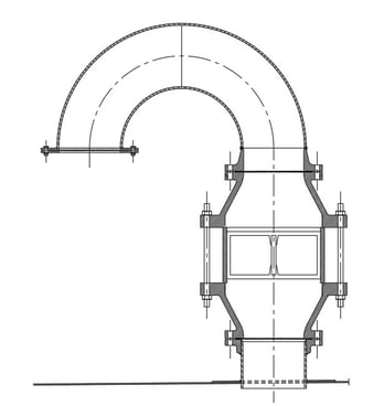
Open Vent with Flame Arrester
Roof Plate
Goose Neck
Flame Arrester
Roof Plate
5. Operating Pressure and Design Pressure
5.1. Fixed roof tanks
These tanks operate at atmospheric pressures or small internal pressures, up to 18 kPa (2.5 psi). The cases are detailed below:
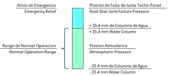
5.1.1 Case 1: Tank with open vent and frangible roof-shell joint
Operating pressure and internal design pressure are considered atmospheric.
Open vents meet requirements with a pressure drop of ±25.4 mm (1") of water column.
The roof-shell joint is designed to fail in a controlled manner in the event of an external fire, so no emergency venting is required.
The tank designer shall calculate the failure pressure of the roof-shell joint and verify that the tank can operate smoothly under this condition.
The criterion of ± 25.4 mm (1") water column is due to the fact that API 650 does not require additional calculations for these design pressures
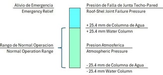
5.1.2 Case 2: Tank with open vent without frangible roof-shell joint
In this case, the installation of an emergency vent is required
Operating pressure: Atmospheric.
Emergency vent setting pressure: It must be greater than 25.4 mm of water column to prevent the emergency vent from opening and closing intermittently.
Internal Design Pressure: Design internal pressure is calculated as:
Pd = Pa + ΔPv + S
Where:
Pa: Emergency vent adjustment pressure.
ΔPv: pressure drop in the emergency vent.
S: margin of safety.


5.1.3 Case 3: Tank with pressure and vacuum valve with frangible roof-shell joint
Operating pressure: Generally, it is estimated as 70% of the valve setting pressure.
Internal design pressure: It is set as 200% of the valve setting pressure, ensuring a sufficient safety margin.
The roof-shell joint is designed to fail in a controlled manner in the event of an external fire. The failure pressure of the roof-shell joint should be calculated by the tank designer and should be less than the internal design pressure of the tank.
Design vacuum pressure: It is set as 200% of the valve setting pressure, this pressure should be greater than the valve pressure at 100% vacuum flow.
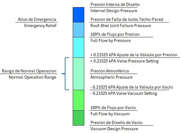
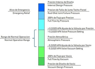
For example, if the pressure and vacuum valve setting pressure is ± 0.21525 kPa (0.865" water column)
Operating pressure: 70% x 0.21525 kPa (0.865" water column) = 0.15 kPa (0.606" water column)
Internal design pressure: 200% x 0.21525 kPa (0.865" water column) = 0.431 kPa (1.73" water column).
Vacuum design pressure: 200% x - 0.21525 kPa (- 0.865" water column) = - 0.431 kPa (- 1.73" water column).
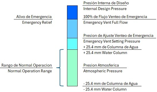
5.1.4 Case 4: Tank with pressure valve and vacuum without frangible roof-shell joint
Operating Pressure: 70% of the pressure and vacuum valve setting pressure.
Emergency vent setting pressure: This must be greater than the pressure and vacuum valve setting pressure, plus the pressure drop in the pressure valve plus a safety percentage to prevent the emergency vent from opening and closing intermittently.
Internal design pressure: Must be higher than emergency vent pressure at 100% flow, with an additional margin of safety. This pressure must be greater than the failure pressure of the roof-wall joint.
Design vacuum pressure: It is set as 200% of the valve setting pressure, this pressure should be greater than the valve pressure at 100% vacuum flow.
For example, if the pressure and vacuum valve setting pressure is ± 0.21525 kPa (0.865" water column) and the pressure drop in the pressure is also +0.21525 kPa (0.865' water column)
Operating pressure: 70% x 0.21525 kPa (0.865" water column) = 0.15 kPa (0.606" water column).
Emergency vent setting pressure: 200% x 0.21525 kPa (0.865" water column) = 0.431 kPa (1.73" water column) plus a percentage to prevent emergency vent from opening and closing intermittently. From the above we will consider emergency vent adjustment pressure of = 0.498 kPa (2" water column)
Internla design pressure: For an emergency vent setting pressure of = 0.498 kPa (2" water column) and considering a pressure drop of 0.498 kPa (2" water column), we would have an internal tank design pressure of approximately 1.1 kPa (4.4" water column, above calculated with a 10% safety factor (2 x 0.498 x1.1 kPa).
Vacuum Design Pressure: 200% x - 0.21525 kPa (- 0.865" water column) = - 0.431 kPa (- 1.73" water column)
5.2. Open-top tanks
Operating and design pressure are considered atmospheric.
External floating roofs include automatic vents that are activated according to the position of the roof, these devices must remain closed while the roof is floating and must be fully open at the time the roof rests on its legs or supporting columns.
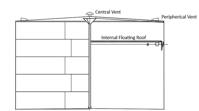
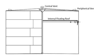
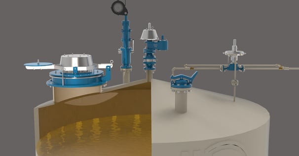
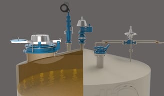
5.3. Fixed roof tanks with internal floating roof
When fixed-roof tanks are equipped with central venting and peripheral circulation vents, as set forth in API 650 H.5.2.2.1 and H.5.2.2.2, both the operating pressure and the internal tank design pressure are considered atmospheric.
If the tank does not have the installation of central circulation and peripheral vents, an alternative system must be implemented to prevent the development of a combustible mixture inside the tank, such as a gas blanketing system or other acceptable method.
In cases where a gas blanketing system is used, it requires the following components:
Gas blanketing regulating valve.
Pressure and vacuum relief valve with flame arresting.
Emergency venting with vacuum relief.
The calculation of operating and design pressures in tanks with gas blanketing will be addressed in another blog, as it requires a detailed consideration of the associated control and safety systems.
6. Conclusions
The correct selection, design, and configuration of atmospheric tanks according to API 650 is key to ensuring safety and efficiency in the storage of liquids. Considering design, operation, and relief pressures, along with the right devices, ensures that tanks meet the most demanding standards.
7. Recommendations
Confirm with the tank designer the operating and design pressures.
In tanks with a brittle joint, verify that the fault pressure is compatible with the expected operating conditions.
The cases analyzed are illustrative, for real cases the valve and vent device manufacturers must verify the valve adjustment pressures and pressure losses to the required vent flow.
8. References and Standards
American Petroleum Institute:
API 650: Welded Tanks for Oil Storage.
API 2000: Venting Atmospheric and Low-pressure Storage Tanks
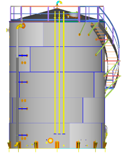
Fixed-Roof Tank with Internal Floating Roof
Details
engineering
info@aceinteca.com
WhatsApp +58 416 6289796
© 2024. All rights reserved.
Technical Information for Tank Equipment Courtesy of World Bridge Industrial Co. Ltd.
Technical Information for Tanks Protection Devices Courtesy of Korea Steel Power Corp.
Technical Information for Bolted Tanks Courtesy of Center Enamel.